By Captain George Stewart, USN (Ret.)
This post provides a basic description of the turboelectric propulsion plant aboard the collier USS Jupiter (AC 3) in its original configuration. Much of this information was obtained from the textbook Practical Marine Engineering (1917) by Captain C.W. Dyson, USN. Additional information was obtained from an article in the 1941 SNAME transactions, titled “Alternating Current in the U.S. Navy,” which was written by LCDR H.G. Rickover, USN. Copies of the ship’s general plans for USS Jupiter in its original configuration as a collier are available on line at www.maritime.org/doc/plans/index.htm.
Jupiter entered service in 1913 as one of a four ship class of colliers. It was, however, the only one of the four with an electric drive installation. The other three ships of the class were all lost at sea. USS Cyclops (AC 4) was lost in 1918 without a trace. USS Proteus (AC 9) and USS Nereus (AC 10) were lost in late 1941. Both were apparently sunk by German U-Boats. At the time, they had been sold to a Canadian company for use in carrying bauxite. Jupiter was later converted into the first US naval aircraft carrier USS Langley (CV 1) in 1920.
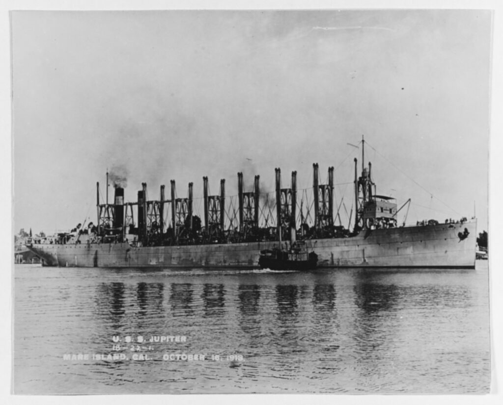
Off the Mare Island Navy Yard, California, 16 October 1913. U.S. Naval History and Heritage Command Photograph. (NH 52365)
In its original form, Jupiter had the following major characteristics:
- Length – 542’
- Beam – 65’
- Draft -27’8”
- Displacement 19,360 Tons
- Complement – 163 personnel
The plant was twin screw with a rating of approximately 6500 SHP. The ship had a sustained speed of approximately 15.5 knots. It represented the first significant application of AC power aboard a US naval vessel. It was essentially an experimental installation. Prior to 1932, all US Naval vessels utilized direct current (DC) in ship service distribution systems and most of the ship’s auxiliary and deck machinery was steam driven. Ship service power aboard Jupiter was supplied from three 35 kW turbine driven DC generators.
The steam turbine was invented in Great Britain by Charles Parsons in 1884. The first marine installation was aboard the SS Turbinia, launched in 1894. By the early 1900s, turbines could be found aboard several large passenger vessels. Several very significant technical obstacles had to be overcome in order to make steam turbines viable for marine applications. The first and most significant was that turbines operate most efficiently at high RPM, while propellers must operate at much lower speeds in order to avoid cavitation. A compromise between efficient turbine and propeller speeds was required. The approach at the time was to add stages to the turbine in order to make it operate more slowly so it could be connected directly to the propeller shaft which then had to be operated at higher than desirable speeds with a subsequent loss in propeller efficiency. Additionally, the turbine rotor diameters had to be quite large, as much as 12 feet in diameter aboard transatlantic liners in order to develop the torque necessary to turn the propeller shafts. By 1910, the navy had begun to experiment with electric and reduction gear drive in order to overcome these issues. However, reduction gear drives in naval vessels did not come to general use until after 1915. Jupiter’s sister ships, USS Cyclops and USS Proteus, were fitted with reciprocating steam engines, while USS Nereus had geared steam turbine drive.
Jupiter’s basic propulsion system consisted of a single 5000 kW AC main turbo-generator driven by a Curtis turbine, two AC induction motors, two water cooled rheostats, and one main switchboard. Excitation for the main generator was obtained from one of the ship’s 35 kW DC ship service turbo-generators. Available information indicates that the total weight of Jupiter’s propulsion plant was 166.5 tons. By comparison, the plant aboard her sister ship USS Cyclops (AC 4) which was propelled by twin reciprocating steam engines, weighed 260.8 tons. The arrangement of the machinery in the engine room is shown in the following diagram:
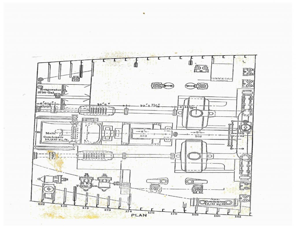 This drawing shows the machinery arrangement on the lower level of Jupiter’s engine room. The port and starboard main propulsion motors and shaft lines can be clearly seen. The motors were located in water tight pits. The main turbo generator set was located on the centerline with the generator located forward of the turbine and the turbine located forward of the main condenser. The three 35 kW DC ship service turbo generators are shown on the starboard side. The two water cooled rheostats were located near the forward bulkhead of the space. The main switchboard and propulsion controls were on the upper level above the rheostats. The propulsion control functions were all performed separately by manually operated switches and levers.
The generator and motors essentially functioned as an electric reduction gear for the main steam turbine. The generator was fitted with two poles, while each motor had 36 poles. This provided a speed reduction of approximately eighteen to one, although the slip of the induction motors resulted in a decrease in RPM of approximately 10% below synchronous speed. As an example, with a turbine speed of 1800 RPM, the actual motor output speed would have been approximately 100 x 90% = 90RPM. After the motors had been started, all changes in motor speed were accomplished by changes in turbine speed, which resulted in a change in generator output frequency. Because both motors were connected to the same generator, the motors could not be varied independently in speed. However, it was possible to operate on a single propulsion motor with significant losses due to wind milling from the idle propeller.
The propulsion motors were of the wound rotor induction type. The motor rotors were fitted with three phase windings which were fitted with external leads via collector rings to the water cooled rheostats. The rheostats were used in order to provide increased torque during starting, reversing and maneuvering operations. The original intent of development of an AC motor of this type was to permit independent control of motor speed and to provide high starting torque without the necessity to vary input frequency. For many years, it found applications on deck machinery aboard ships with AC distribution systems. The only application of a wound motor induction motor that I ever encountered was when I served aboard a minesweeper where it was utilized on the deck winch that was used for streaming and recovering minesweeping gear. The need for propulsion motors of this type has since gone away due to the advent of solid state control devices. Most AC propulsion plants aboard ships built since 1940 have utilized synchronous type AC propulsion motors. DDG 1000, which is under construction, is propelled by four advanced induction motors (AIM), two per shaft. Modern electric drive ships make use of integrated power plants with multiple AC generators supplying both propulsion and ship service power from the same bus. Note that integrated power plants were not practical for many years because of the need to vary generator speed and output frequency in order to control propulsion motor speed.
The Jupiter propulsion plant had two basic operating modes.
- Maneuvering – In this mode, the rheostats were kept into the rotor circuits on both motors in order to provide increased torque during starting and reversing operations. Continuous operation in this mode was uneconomical because of losses associated with the rheostats.
- Cruising – Once the ship had settled down to economical cruising, the operator could cut the rheostats out of the circuit by means of a short circuiting device. All speed changes were then accomplished by varying the main turbo generator speed and output frequency by means of the main turbine governor. As previously mentioned, both motors had to be operated at the same speed, although operation was possible on a single motor with the other motor disabled.
In its original configuration Jupiter was fitted with two double ended coal fired Scotch fire tube boilers that supplied saturated steam at 190 psi. The following illustration shows one of Jupiter’s original boilers being lifted on board during construction:
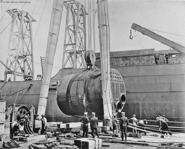
One of Jupiter’s boilers being lifted aboard for installation while fitting out at Navy Yard Mare Island, circa 1912-13. Navy Yard Mare Island photo (NavSource)
Jupiter was converted into the first U.S. aircraft carrier at the Norfolk, VA, Navy Yard for the purpose of conducting experiments in seaborne aviation. The conversion was authorized by Congress in 1919. The ship was decommissioned in March, 1920 and her name was changed to USS Langley (CV 1). The ship was recommissioned as USS Langley (CV 1) in March, 1922. It is assumed that the ship was converted to burn oil during the conversion but this is not specifically stated in any available records. In addition, records indicate that Langley was refitted with three Bureau Type express boilers. Although no specific description of this installation can be found a memorandum written by Langley’s executive officer on 1 February 1923 describing the normal ship’s routine specifically states that all aviation operations will be accomplished with 3 boilers on the line. A change over to water tube boilers would have probably been desirable because the original Scotch fire tube boilers were very sluggish in response to the frequent changes in steam demand that the ship would experience in its’ aircraft carrier role.
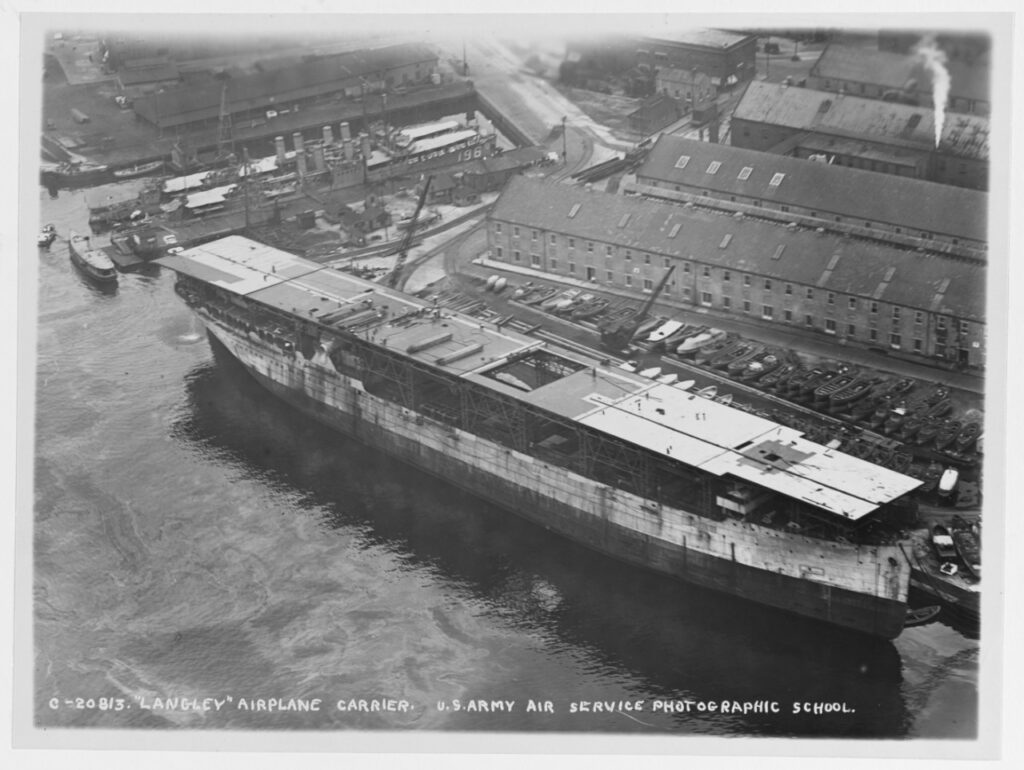
Under reconstruction from the collier JUPITER at Norfolk Navy Yard, Portsmouth, Virginia, circa late 1921. (NHHC Photo # NH 93538)
- Reduction in displacement from 19,360 to 11,500 tons
- Full load draft reduced from 27’8” to 18’11’
- Complement increased from 163 to 468 personnel
A major problem associated with the conversion was smoke dispersal. Jupiter was originally fitted with a single funnel however this was later changed to two funnels. The funnels were located to port and starboard. Obviously this configuration was unsuitable for carrier operations. Therefore, Langley was refitted with a short folding funnel to port and a smoke opening below the flight deck level to starboard. In theory either could be used, depending upon the wind. The starboard opening was fitted with water sprays for cooling. Problems were experienced with this installation and the ship was eventually retrofitted with a pair of hinged funnels on the port side.
Due to the success of the Jupiter installation, AC propulsion systems were subsequently utilized in six battleships that entered service between 1918 and 1923, plus USS Lexington (CV 2) and USS Saratoga (CV 3), both of which entered service in 1927 with four screw plants rated at 180,000 SHP. All subsequent steam turbine installations aboard US naval vessels built after 1927 utilized gear drive, an exception being the 124 destroyer escorts of the Buckley (DE 102) and Rudderow (DE 224) classes that were built during World War II. These plants followed the same general lines as those aboard the 481 MARAD T-2 commercial tankers which entered service during the war. The reason for the use of electric drive aboard these ships was limitations in available gear manufacturing capacity and priority had to be given to destroyers and large combatants which had much higher power requirements. In recent years, electric drive has experienced a rebirth with integrated plants aboard cruise liners, some naval auxiliaries, and the upcoming USS Zumwalt (DDG 1000) which just completed acceptance trials. When compared to gear drive electric drive has some disadvantages, including greater cost and complexity, increased space requirements and lower transmission efficiency. However, it is very suitable for ships with large auxiliary loads that spend extended periods at low cruising speeds. The use of integrated electric drive has become virtually universal in the cruise liner industry.
By the mid 1930s, a number of large aircraft carriers had joined the fleet and due to her small size and slow speed Langley was no longer needed as a carrier. In 1937, the ship was converted into a seaplane tender (AV-3). The ship was sunk by Japanese aircraft off the coast of Java in 1942.
In summary, Langley played a very important part in the development of naval aviation and its propulsion plant served as a model for future development.
George W. Stewart is a retired US Navy Captain. He is a 1956 graduate of the Massachusetts Maritime Academy. During his 30 year naval career, he held two ship commands and served a total of 8 years on naval material inspection boards, during which he conducted trials and inspections aboard over 200 naval vessels. Since his retirement from active naval service in 1986 he has been employed in the ship design industry where he has specialized in the development of concept designs of propulsion and powering systems, some of which have entered active service. He currently holds the title of Chief Marine Engineer at Marine Design Dynamics.

Steve
Gijs van der Starre